About Time: Sifting Through Analog Video Terminology

In case it's ever unclear, writing these blog posts is as much for me as it is for you, dear reader. Technical audiovisual and digital concepts are hard to wrap your head around, and for a myriad of reasons technical writing is frequently no help. Writing things out, as clearly and simply as I can, is as much a way of self-checking that I actually understand what's going on as it is a primer for others.
And it case this intro is unclear, this is a warning to cover my ass as I dive into a topic that still trips me up every time I try to walk through it out loud. I'll provide references as I can at the end of the piece, but listen to me at your own risk.
When I first started learning about preserving analog video, *most* of what I was reading/talking about made a certain amount of sense, which is to say it at least translated into some direct sensory/observable phenomenon - luminance values made images brighter or darker, mapping audio channels clearly changed how and what I was hearing, using component video rather than composite meant mucking around with a bunch more cables. But when we talked about analog signal workflows, there always seemed to be three big components to keep track of: video (what I was seeing), audio (what I was hearing) and then this nebulous goddamn thing called "sync" that I didn't understand at all but seemed very very important.

I do not know who to blame for the morass of analog video signal terms and concepts that all have to do in some form with "time" and/or "synchronization". Most likely, it's just an issue at the very heart of the technology, which is such a marvel of mechanical and mathematical precision that even as OLED screens become the consumer norm I'm going to be right here crowing about how incredible it is that CRTs ever are/were a thing. What I do know is that between the glut of almost-but-not-quite-the-same words and devices that do almost-but-not-quite-the-same-thing-except-when-they're-combined-and-then-they-DO-do-the-same-thing, there's a real hindrance to understanding how to put together or troubleshoot an analog video digitization setup. Much of both the equipment and the vocabulary that we're working with came from the needs of production, and that has led to some redundancies that don't always make sense coming from the angle of either preservation or casual use.

So I'm going to offer a guide here to some concepts and equipment that I've frequently seen either come up together or understandably get confused for each other. That includes in particular:
- sync and sync generators
- time base correction
- genlock
- timecode
...though other terms will inevitably rise as we go along. I'm going to assume a certain base level of knowledge with the characteristics and function of analog video signal - that is, I will write assuming the reader has been introduced to electron guns, lines, fields, frames, interlacing, and the basics of reading a classic/default analog video waveform. But I will try not to ever go right into the deep end.
Sync/Sync Generators
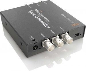
I know I just said I would assume some analog video knowledge, but let's take a moment to contemplate the basics, because it helps me wrap my head around sync generators and why they can be necessary.
Consider the NTSC analog video standard (developed in the United States and employed in North, Central and parts of South America). According to NTSC, every frame of video has two fields, each consisting of 262.5 scan lines - so that's 525 scan lines per frame. There are also 29.97 frames of video per second.
That means the electron gun in a television monitor has to fire off 15734.25 lines of video PER SECOND - and that includes not just actually tracing the lines themselves, but the time it takes to reset both horizontally (to start the next line) and vertically (to start the next field).
Now throw a recording device into the mix. At the same time that a camera is creating that signal and a monitor is playing it back, a VTR/VCR has to receive that signal and translate it into a magnetic field stored on a constantly-moving stretch of videotape via an insanely quick-spinning metal drum.
Even in the most basic of analog video signal flows, there are multiple devices (monitor, playback/recording device, camera, etc.) here that need to have an extremely precise sense of timing. The recording device, for instance, needs to have a very consistent internal sense of how long a second is, in order for all its tiny little metal and plastic pieces to spin and roll and pulse in sync (for a century, electronic devices, either analog OR digital, have used tiny pieces of vibrating crystal quartz to keep track of time - which is just a whole other insane tangent). But, in order to achieve the highest quality signal flow, it also needs to have the exact same sense of how long a second is as the camera and the monitor that it's also hooked up to.
When you're dealing with physical pieces of equipment, possibly manufactured by completely different companies at completely different times from completely different materials, that's difficult to achieve. Enter in sync signal and sync generators.

Sync generators essentially serve as a drumbeat for an analog video system, pumping out a trusted reference signal that all other devices in the signal chain can use to drive their work instead of their own internal sense of timing. There are two kinds of sync signals/pulses that sync generators have historically output:
Drive pulses were almost exclusively used to trigger certain circuits in tube cameras, and were never part of any broadcast/recorded video signal. So you're almost certainly never going to need to use one in archival digitization work, but just in case you ever come across a sync generator with V. Drive and H. Drive outputs (vertical drive and horizontal drive pulses), that's what those are for.
Blanking pulses cause the electron gun on a camera or monitor to go into its "blanking" period - which is the point at which the electron gun briefly shuts off and retraces back to the beginning of a new line (horizontal blanking) or of a new field (vertical blanking). These pulses are a part of every broadcast/recorded video signal, and they must be extremely consistent to maintain the whole 525-scan-lines-29.97-times-per-second deal.
Since blanking pulses are the vast majority of modern sync signals, you may also just see these referred to as "sync pulses".
So the goal of sync generators is to output a constant video signal with precise blanking pulses that are trusted to be exactly where (or to be more accurate, when) they should be. Blanking pulses are contained in the "inactive" part of a video signal, meaning they are never meant to actually be visualized as image on a video camera or monitor (unless for troubleshooting purposes) - so it literally does not matter what the "active" part of a sync generator's video signal is. It could just be field after field, frame after frame of black (often labeled "black burst"). It could be some kind of test pattern - so you will often see test pattern generators that double as or are used as sync generators, even though these are separate functions/purposes, and thus could also be entirely separate devices in your setup.

(To belabor the point, test patterns, contained in the "active" part of the video signal, can be used to check the system, but they do not drive the system in the same way that the blanking pulses in the "inactive" part of a signal do. IMHO, this is an extremely misleading definition of "active" and "inactive", since both parts are clearly serving crucial roles to the signal, and what is meant is just "seen" or "unseen".)
Here's the kicker - strictly speaking, sync generators aren't absolutely necessary to a digitization station. It's entirely possible that you'll hook up all your components and all the individual pieces of equipment will work together acceptably - their sense of where and when blanking pulses should fall might already be the same, or close enough to be negligible.
But maybe you're seeing some kind of a wobbling or inconsistent image. That *could* be a sync issue, with one of your devices (the monitor, e.g.) losing its sense of proper timing, and resolvable by making sure all devices are working off the same, trusted sync generator.
You'll see inputs for sync signal labeled in all sorts of inconsistent ways on analog video devices: "Sync In", "Ext Sync", "Ext Ref", "Ref In", etc. As far as I'm aware, these all mean the same thing, and references in manuals or labels to "sync signal" or "reference signal" should be treated interchangeably.
Time Base Correction
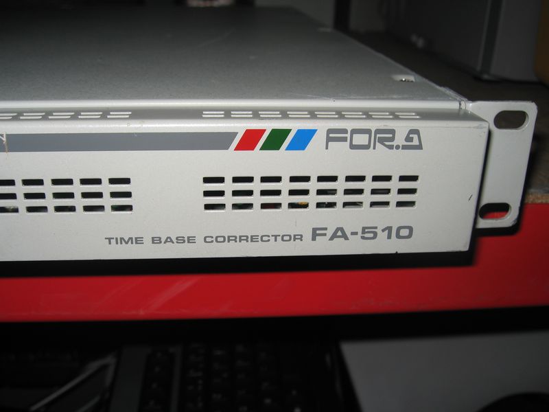
Sync generators can help line up devices with inconsistent timing in a system as a video signal is passed from one to another. Time Base Correctors (TBCs) perform an extremely similar but ever-so-confusingly-different task. TBCs can take an input video signal, strip out inconsistent sync/blanking pulses, and replace them entirely with new, steady ones.
This is largely necessary when dealing with pre-recorded signals. Consider a perfectly set up, synced recording system: using a CRT for the operator to monitor the image, a video camera passed a video signal along to a VTR, which recorded that signal on to magnetic tape. At the time, a sync generator made sure all these devices worked together seamlessly. But now, playing back that tape for digitization, we've introduced the vagaries of magnetic tape's physical/chemical makeup into the mix. Perhaps it's been years and the tape has stretched or bent, the metallic particles have expanded or compressed - not enough to prevent playback, but enough to muck with the sync pulses that rely on precision down to millionths of a second. As described with sync loss above, this usually manifests in the image looking wobbly, improperly framed or distorted on a monitor, etc.

TBCs can either use their own internal sense of time to replace/correct the timing of the sync pulses on the recorded video signal - or they can use the drumbeat of a sync generator as a reference, to ensure consistency within a whole system of devices.
(Addendum): A point I'm still not totally clear on is the separation (or lack thereof) between time base correction and frame synchronization. According to the following video I found, a stand-alone frame synchronizer could stabilize the vertical blanking pulses in a signal only, resulting in a solid image at the moment of transition from one frame to another (that is, the active video image remains properly centered vertically within a monitor), but did nothing for horizontal sync pulses, potentially resulting in line-by-line inconsistencies:
So time base correction would appear to incorporate frame synchronization, while adding the extra stabilization of consistent horizontal sync/blanking pulses.
While, as I said above, you can very often get away with digitizing video without a sync generator, TBCs are generally much more critical. It depends on what analog video format you're working with exactly, but whereas the nature of analog devices meant there was ever so slight leeway to deal with those millionth-of-a-second inconsistencies (say, to display a signal on a CRT), the precise on-or-off, one-or-zero nature of digital signals means analog-to-digital converters usually need a very very steady signal input to do their job properly.
You may however not need an external TBC unit. Many video playback decks had them built in, though of varying quality and performance. If you can, check the manual for your model(s) to see if it has an internal TBC, and if so, if it's possible to adjust or even turn it off if you have a more trustworthy external unit.
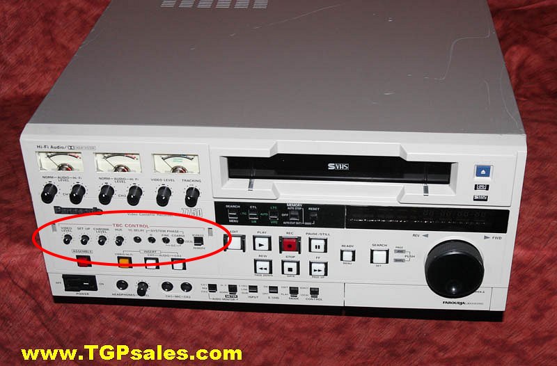
Technically there are actually three kinds of TBCs: line, full frame and full field. Line TBCs can only sample, store and correct errors/blanking pulses for a few lines of video at a time. Full field TBCs can handle, as the name implies, a full 262.5 (NTSC) lines of video at a time, and full frame TBCs can take care a whole frame's worth (525, NTSC) of lines at a time. "Modern", late-period analog TBCs are pretty much always going to be full frame, or even capable of multiple frames' worth of correction at a time (this is good for avoiding delay and sync issues in the system if working without a sync generator). This will likely only come into play with older TBC units.
And here's one last thing that I found confusing about TBCs given the particular equipment I was trained on: this process of time base correction, and TBCs themselves, has nothing to do with adjusting the qualities of the active image itself. Brightness, saturation, hue - these visible characteristics of video image are adjusted using a device called a processing amplifier or proc amp.
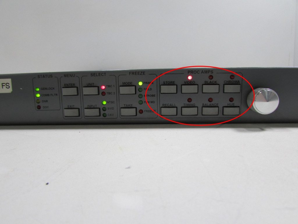
Because the process of replacing or adjusting sync pulses is a natural moment in a signal flow to ALSO adjust active video signal levels (may as well do all your mucking at once, to limit troubleshooting if something's going wrong), many external TBC units also contain proc amps, thus time base correction and video adjustments are made on the same device, such as the DPS TBC unit above. But there are two different parts/circuit boards of the unit that are doing these two tasks, and they can be housed in completely separate devices as well (i.e. you may have a proc amp that does no time base correction, or a TBC that offers no signal level adjustments).
Genlock
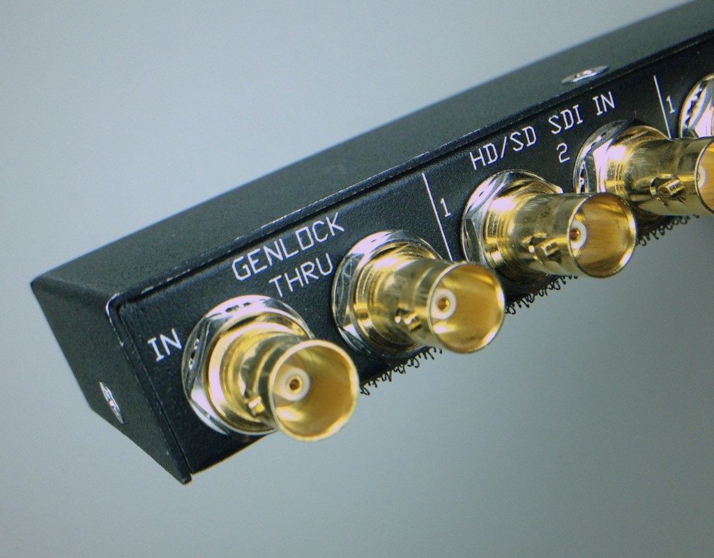
"Genlock" is a phrase and label that you may see on various devices like TBCs, proc amps, special effects generators and more - often instead of or in the same general place you would see "Sync" or "Ref" inputs. What's the deal here?
This term really grew out of the production world and was necessary for cases where editors or broadcasters were trying to mix two or more input video signals into one output. When mixing various signals, it was again good/recommended practice to choose one as the timing reference - all the other input signals, output, and special effects created (fades, added titles, wipes, etc. etc.) would be "locked" on to the timing of the chosen genlock input (which might be either a reference signal from a sync generator, or one of the actually-used video inputs). This prevented awkward "jumps" or other visual errors when switching between or mixing the multiple signals.
In the context of a more straightforward digitization workflow, where the goal is not to mix multiple signals together but just pass one steadily all the way through playback and time base correction to monitoring and digitization, "genlock" can be treated as essentially interchangeable with the sync signal we discussed in the "Sync/Sync Generators" section above. If the device you're using has a genlock input, and you're employing a sync generator to provide an external timing reference for your system, this is where you would connect the two.
Timecode
The signals and devices that I've been describing have been all about driving machinery - time base is all about coordinating mechanical and electrical components that function down at the level of milliseconds.
Timecode, on the other hand, is for people. It's about identifying frames of video for the purpose of editing, recording or otherwise manipulating content. Unlike film, where if absolutely need be a human could just look at and individually count frames to find and edit images on a reel, magnetic tape provides no external, human-readable sense of what image or content is located where. Timecode provides that. SMPTE timecode, probably the most commonly used standard, identified frames according to a clock-based system formatted "00:00:00:00", which translated to "Hours:Minutes:Seconds:Frames".
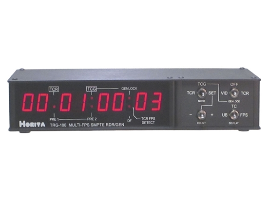
Timecode could be read, generated, and recorded by most playback/recording/editing devices (cameras or VTRs), but there were also stand-alone timecode reader/generator boxes created (such as in the photo above) for consistency and stability's sake across multiple recording devices in a system.
There have been multiple systems of recording and deploying timecode throughout the history of video, depending on the format in question and other concerns. Timecode was sometimes recorded as its own signal/track on a videotape, entirely separate from the video signal, in the same location as one might record an audio track. This system was called Linear Timecode (LTC). The problem with LTC was, like with audio tracks, the tape had to be in constant motion to read the timecode track (like how you can not keep hearing an audio signal when you pause it, even though you *can* potentially keep seeing one frame of image when a video signal is paused on one line).
Vertical Interval Timecode (VITC) fixed this (and had the added benefit of freeing up more physical space on the tape itself) by incorporating timecode into video signal itself, in a portion of the inactive, blanking part of the signal. This allowed systems to read/identify frame numbers even when the tape was paused.
Other systems like CTL timecode (control track) and BITC (timecode burnt-in to the video image) were also developed, but we don't need to go too far into that here.
As long as we're at it, however, I'd also like to quickly clarify two more terms: drop-frame and non-drop-frame timecode. These came about from a particular problem with the NTSC video standard (as far as I'm aware, PAL and SECAM do not suffer the same, but please someone feel free to correct me). Since NTSC video plays back at the frustratingly non-round number of 29.97 frames per second (a number arrived at for mathematical reasons beyond my personal comprehension that have something to do with how the signal carries color information), the timecode identifying frame numbers will eventually drift away from "actual" clock time as perceived/used by humans. An "hour of timecode" which by necessity must count upwards at a 30 fps rate such as:
00:00:00:28
00:00:00:29
00:00:01:00
00:00:01:01
played back at 29.97 fps, will actually be 3.6 seconds longer than "wall-clock" time.
That's already an issue at an hour, and proceeds to get worse the longer the content being recorded. So SMPTE developed "drop-frame" timecode, which confusingly does not drop actual frames of video!! Instead, it drops some of the timecode frame markers. Using drop-frame timecode, our sequence would actually proceed thus:
00:00:00;28
00:00:00;29
00:00:01;02
00:00:01;03
With the ":00" and ":01" frame markers removed entirely from the timecode; except for every tenth minute, when they are re-inserted to make the math check out:
00:00:09;28
00:00:09;29
00:00:10;00
00:00:10;01
Non-drop-frame timecode simply proceeds as normal, with the potential drift from clock time. Drop-frame timecode is often (but not necessarily - watch out) identified in video systems using semi-colons or single periods instead of colons between the second and frame counts, as I have done above. Semi-colons are common on digital devices, while periods are common on VTRs that didn't have the ability to display semi-colons.
I hope this journey through the fourth dimension of analog video clarifies a few things. While each of these concepts is reasonable enough on their own, the way they relate to each other is not always clear, and the similarity in terms can send your brain down the wrong alley quickly. Happy digitizing!
Resources
Andre, Adam. "Time Base Corrector." Written for NYU-MIAP course in Video Preservation I, Fall 2017. Accessed 6/9/2018. https://www.nyu.edu/tisch/preservation/program/student_work/2017fall/17f_3403_Andre_a1.pdf
"Genlock: What is it and why is it important?" Worship IMAG blog. Posted 6/11/2011. Accessed 6/8/2018. https://worshipimag.com/2011/06/11/gen-lock-what-is-it-and-why-is-it-important/
Marsh, Ken. Independent Video. San Francisco, CA: Straight Arrow Books, 1974.
Poynton, Charles. Digital Video and HD: Algorithms and Interfaces. 2nd edition. Elsevier Science, 2012.
SMPTE timecode. Wikipedia. Accessed 6/8/2018.
Weise, Marcus and Diana Weynand. How Video Works: From Analog to High Definition. 2nd Edition. Burlington, MA: Focal Press, 2013.
