See What You Hear: Audio Calibration for Video Digitization
I've always been amused by the way a certain professional field frequently goes out of its way to shout "we don't understand audio" to the world. (Association of Moving Image Archivists, Moving Image Archiving and Preservation, Moving Image Archive Studies, Museum of the Moving Image, etc. etc.)
"But there's no good word to quickly cover the range of media we potentially work with," you cry! To which I say, "audiovisual" is a perfectly good format-agnostic term that's been in the public consciousness for decades and doesn't confuse my second cousins when I try to explain what I do. "But silent film!" you counter, trying to use clever technicalities. To which I say, silent film was almost never really silent, home movies were meant to be narrated over, and stop being a semantic straw man when I'm trying to have a hot take over here!
The point is: when working in video preservation and digitization, our training and resources have a tendency to lean toward "visual" fidelity rather than the "audio" half of things (and it IS half). I'm as guilty of it as anyone. As I've described before, I'm a visual learner and it bleeds into my understanding and documentation of technical concepts. So I'm going to take a leap and try and address another personal Achilles' heel: audio calibration, monitoring, and transfer for videotape digitization.
I hope this to be the first in an eventual two-part post (though both halves can stand alone as well). Today I'll be talking about principles of audio monitoring: scales, scopes and characteristics to watch out for. Tune in later for a breakdown of format-by-format tips and tricks that vary depending on which video format you're working with: track arrangements, encoding, common errors, and more. My focus, for now, is on audio in regards to videotape - audio-only formats like 1/4" open reel, audio cassette, vinyl/lacquer disc and more bring their own concerns that I won't get into right now, if only for the sake of scope crawl (I've been writing enough 3000+ word posts of late). But much if not all of the content in this post particularly should be applicable to audio-only preservation as well!
Big thanks to Andrew Weaver for letting me pick his brain and help spitball these posts!
The Spinal Tap Problem
Anyone who has ever attended one of my workshops knows that I love to take a classic bit of comedy and turn it into a buzz-killing object lesson. So:
Besides an exceptional sense of improvisational timing, what we have here is an excellent illustration of a fundamental disconnect in audio calibration and monitoring: the difference between how audio signal is measured (e.g. on a scale of 1 to 10) and how it is perceived ("loudness").
There are two places where we can measure or monitor audio: on the signal level (as the audio passes through electrical equipment and wires, as voltage) or on the output level (as it travels through the air and hits our ears as a series of vibrations). We tend to be obsessed with the latter - judging audio based on whether it's "too quiet" or "too loud", which strictly speaking is as much a matter of presentation as preservation. Cranking the volume knob to 11 on a set of speakers may cause unpleasant aural side effects (crackling, popping, bleeding eardrums) but the audio signal as recorded on the videotape you're watching stays the same.
To be clear, this isn't actually any different than video signal: as I've alluded to in past posts, a poorly calibrated computer monitor can affect the brightness and color of how a video is displayed regardless of what the signal's underlying math is trying to show you. So just as we use waveform monitors and vectorscopes to look at video signals, we need "objective" scales and monitors to tell us what is happening on the signal level of audio to make sure that we are accurately and completely transferring analog audio into the digital realm.
Just like different color spaces have come up with different scales and algorithms for communicating color, different scales and systems can be applied to audio depending on the source and/or characteristic in question. Contextualizing and knowing how to "read" exactly what these scales are telling us is something that tends to get lost by the wayside in video preservation, and what I'm aiming to demystify a bit here.
Measuring Audio Signal
So if we're concerned with monitoring audio on the signal level - how do we do that?
All audiovisual signal/information is ultimately just electricity passed along on wires, whether that signal is interpreted as analog (a continuous wave) or digital (a string of binary on/off data points). So at some level measuring a signal quantitatively (rather than how it looks or sounds) always means getting down and interpreting the voltage: the fluctuations in electric charge passed along a cable or wire.
In straight scientific terms, voltage is usually measured in volts (V). But engineers tend to come up with other scales to interpret voltage that adjust unit values and are thus more meaningful to their own needs. Take analog video signal, for instance: rather than volts, we use the IRE scale to talk about, interpret and adjust some of the most important characteristics of video (brightness and sync).
We never really talk about it in these terms, but +100 IRE (the upper limit of NTSC's "broadcast range", essentially "white") is equivalent to 700 millivolts (0.7 V). We *could* just use volts/millivolts to talk about video signal, but the IRE scale was designed to be more directly illustrative about data points important to analog video. Think of it this way: what number is easier to remember, 100 or 700?

Audio engineers had the same conundrum when it came to analog audio signal. Where it gets super confusing from here is that many scales emerged to translate voltage into something useful for measuring audio. I think the best way to proceed from here is just to break down the various scales you might see and the context for/behind them.
dBu/dBv
Decibel-based scales are logarithmic rather than linear, which makes them ideal for measuring audio signals and vibrations - the human ear is more sensitive to certain changes in frequency and/or amplitude than others, and a logarithmic scale can better account for that (quite similar to gamma correction when it comes to color/luminance and the human eye).
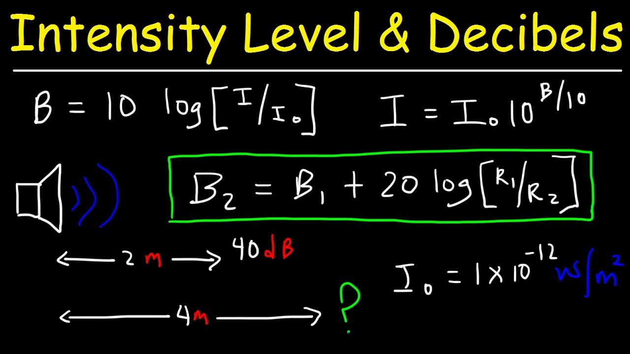
The problem is that decibels are also a relative unit of measurement: something can not just be "1 dB" or "1000 dB" loud; it can only be 1 dB or 1000 dB louder than something else. So you can see quite a lot of scales related to audio that start with "dB" but then have some sort of letter serving as a suffix; this suffix specifies what "sound" or voltage or other value is serving as the reference point for that particular scale.
An extremely common decibel-based scale for measuring analog audio signals is dBu. The "u" value in there stands for an "unterminated" voltage of 0.775 volts (in other words, the value "+1 dBu" stands for an audio wave that is 1 decibel louder than the audio wave generated by a sustained voltage of 0.775 V).
In the analog world, dBu is considered a very precise unit of measurement, since it was based on electrical voltage values rather than any "sound", which can get subjective. So you'll see it in a lot of professional analog audio applications, including professional-grade video equipment.
Confusingly: "dBu" was originally called "dBv", but was re-named to avoid confusion with the next unit of measurement on this list. So yes, it is very important to distinguish whether you are dealing with a lower-case "v" or upper-case "V". If you see "dBv", it should be completely interchangeable with "dBu" (...unless someone just wrote it incorrectly).
dBV
dBV functions much the same as dBu, except the reference value used is equivalent to exactly 1 volt (1 V). It is also used as a measurement of analog audio signal. (+1 dBV indicates an audio wave one decibel louder than the wave generated by a sustained voltage of 1 V)
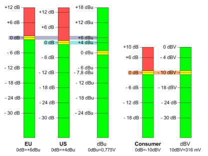
Now...why do these two scales exist, referenced to slightly different voltages? Honestly, I'm still a bit mystified myself. Explanations of these reference values delve quite a bit into characteristics of electrical impedance and resistance that I don't feel adequately prepped/informed enough to get into at the moment.
What you DO need to know is that a fair amount of consumer-grade analog audiovisual equipment was calibrated according to and uses the dBV scale instead of dBu. This will be a concern if you're figuring out how to properly mix and match and set up equipment, but let's table that for a minute.
PPM and VU
dBu and dBV, while intended for accurately measuring audio signal/waves, still had a substantial foot in the world of electrical signal/voltage, as I've shown here. Audio engineers still wanted their version of "IRE": a reference scale and accompanying monitor/meter that was most useful and illustrative for the practical range of sound and audio signal that they tended to work with. At the time (~1930s), that meant radio broadcasting, so just keep that in mind whenever you're flipping over your desk in frustration trying to figure out why audio calibration is the way it is.
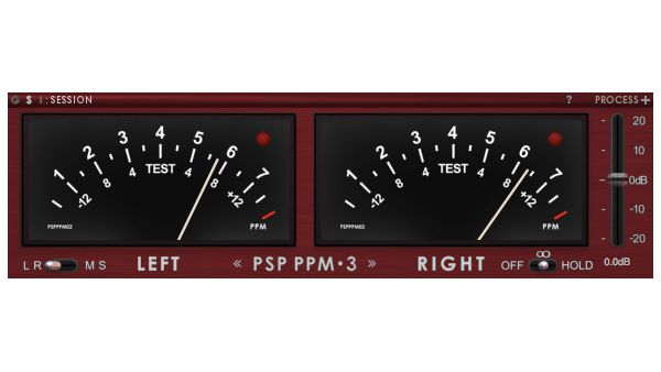
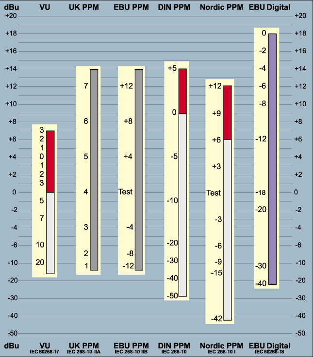
In the United States, however, audio/radio engineers decided that PPM would be too expensive to implement, and instead came up with VU meters. VU stands for Volume Units (not, as I thought myself for a long time, "voltage units"!!! VU and V are totally different units of scale/measurement).
VU meters are averaged, which means they don't so much give a precise reading of the peaks of audio waves so much as a generalized sense of the strength of the signal. Even though this meant they might miss certain fluctuations (a very quick decibel spike on an audio wave might not fully register on a VU meter if it is brief and unsustained), this translated close enough to perceived loudness that American engineers went with this lower-cost option. VU meters (and the Volume Unit scale that accompany it) are and always have been intended to get analog audio "in the ballpark" rather than give highly accurate readings - you can see this in the incredibly bad low-level sensitivity on most VU meters (going from, say, -26 VU to -20 VU, for instance, is barely going to register a blip on your needle).
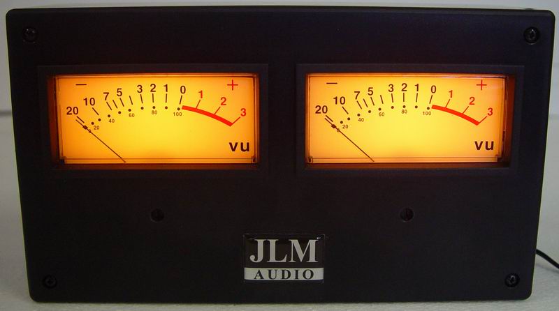
So I've lumped these two scales/types of meter together because you're going to see them in similar situations (equipment for in-studio production monitoring for analog A/V), just generally varying by your geography. From here on out I will focus on VU because it is the scale I am used to dealing with as an archivist in the United States.
dBFS
All of these scales I've described so far have related to analog audio. If the whole point of this post is to talk about digitizing analog video formats...what about digital audio?
Thankfully, digital audio is a little more straightforward, at least in that there's pretty much only one scale to concern yourself with: dBFS ("decibels below [or in relation to] Full Scale").

Whereas analog scales tend to use relatively "central" reference values - where ensuing audio measurements can be either higher OR lower than the "zero" point - the "Full Scale" reference refers to the point at which digital audio equipment simply will not accept any higher value. In other words, 0 dBFS is technically the highest possible point on the scale, and all other audio values can only be lower (-1 dBFS, -100 dBFS, etc. etc.), because anything higher would simply be clipped: literally, the audio wave is just cut off at that point.
Tipping the Scales
All right. dBu, dBV, dBFS, VU....I've thrown around a lot of acronyms and explanations here, but what does this all actually add up to?
If you take away anything from this post, remember this:
0 VU = +4 dBu = -20 dBFS
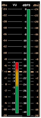
The only way to sift through all these different scales and systems - the only way to take an analog audio signal and make sure it is being translated accurately into a digital audio signal - is to calibrate them all against a trusted, known reference. In other words - we need a reference point for the reference points.
In the audio world, that is accomplished using a 1 kHz sine wave test tone. Like SMPTE color bars, the 1 kHz test tone is used to calibrate all audio equipment, whether analog or digital, to ensure that they're all understanding an audio signal the same way, even if they're using different numbers/scales to express it.
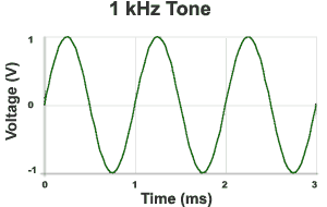
In the analog world, this test tone is literally the reference point for the VU scale - so if you play a 1 kHz test tone on equipment with VU meters, it should read 0 VU. From there, the logarithms and standards demand that 0 VU is the same as +4 dBu. That is where the test tone should read if you have equipment that uses those scales.
dBFS is a *little* more tricky. It's SMPTE-recommended practice to set 1 kHz test tone to read at -20 dBFS on digital audio meters - but this is not a hard-and-fast standard. Depending on the context, some equipment (and therefore the audio signals recorded using them) are calibrated so that a 1 kHz test tone is meant to hit -18 or even -14 dBFS, which can throw the relationship between your scales all out of whack.
(In my experience, however, 99 times out of 100 you will be fine assuming 0 VU = -20 dBFS)
Once you're confident (relatively) that everyone's starting in the same place, that makes it possible to proceed from there: audio signals hitting between 0 and +3 VU on VU meters, for example, should be hitting roughly between -20 dBFS and -6 dBFS on a digital scale.
Note that these are all logarithmic scales based on different logarithms - so they are never going to line up one-to-one except at the agreed-upon reference point. That is, +4 dBu may be equal to 0 VU, but +5 dBu is not equal to 1 VU. When it comes to translating audio signal from one system and scale to another, we can follow certain guidelines and ranges, but there is always going to be a certain amount of imprecision and subjectivity in working with these scales on a practical level during the digitization process.
Danger, Will Robinson
Remember when I said that we were talking about signal level, not necessarily output level, in this post? And then I said something about how professional equipment calibrated to the dBu scale versus how consumer equipment calibrated to dBV scale? Sorry. Let's circle back to that for a minute.
Audio equipment engineers and manufacturers didn't stop trying to cut corners when they adopted the VU meters over PPM. As a cost-saving measure for wider consumer releases, they wanted to make audio devices with ever-cheaper physical components. Cheaper components literally can't handle as much voltage passing through them as higher-quality, "professional-grade" components and equipment.

So many consumer-grade devices were calibrated to output a 1 kHz test tone audio signal at -10 dBV, which is equivalent to a significantly lower voltage than the professional, +4 dBu standard.
(The math makes my head hurt, but you can walk through it in this post; also, I get the necessary difference in voltage but no, I still don't really understand why this necessitated a difference in the decibel scale used)
What this means is: if you're not careful, and you're mixing devices that weren't meant to work together, you can output a signal that is too strong for the input equipment to handle (professional -> consumer), or way weaker than it should be (consumer -> professional). I'll quote here the most important conclusion from that post I just linked above:
If you plug a +4dBu output into a -10dBV input the signal is coming in 11.79dB hotter than the gear was designed for... turn something down.If you plug a -10dBV output into a +4dBu input the signal is coming in 11.79dB quieter than the gear was designed for... turn something up.
Unbalanced audio signal/cables are a big indicator of equipment calibrated to -10 dBV: so watch out for any audio cables and connections you're making with RCA connectors.
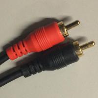
The reality is also that after a while many professional-grade manufacturers were aware of the -10 dBV/+4 dBu divide, and factored that into their equipment: somewhere, somehow (usually on the back of your device, perhaps on an unmarked switch) is the ability to actually swap back and forth between expecting a -10 dBV input and a +4 dBu one (thereby making any voltage gain adjustments to give you your *expected* VU/dBFS readings accordingly). Otherwise, you'll have to figure out a way to make your voltage gain adjustments yourself.
The lessons are two-fold:
- Find a manual and get to know your equipment!!
- You can plug in consumer to professional equipment, but BE CAREFUL going professional into consumer!! It is possible to literally fry circuits by overloading them with the extra voltage and cause serious damage.
Set Phase-rs to Stun
There's another thing to watch out for while we're on the general topic of balanced and unbalanced audio, which are the concepts of polarity and phase.
Polarity is what makes balanced audio work; it refers to the relation of an audio signal's position to the median line of voltage (0 V). Audio sine waves swing from positive voltage to negative voltage and vice versa -precisely inverting the polarity of a wave (i.e. taking a voltage of +0.5 V and flipping it to -0.5 V) and summing those two signals together (playing them at the same time) results in complete cancellation.

Professional audio connections (those using XLR cables/connections) take advantage of this quality of polarity to help eliminate noise from audio signals (again, you can read my post from a couple years back to learn more about that process). But this relies on audio cables and equipment being correctly wired: it's *possible* for technicians, especially those making or working with custom setups, to accidentally solder a wire such that the "negative" wire on an XLR connector leads to a "positive" input on a deck or vice versa.

This would result in all kinds of insanely incorrectly-recorded signals, and probably caught very quickly. But it's a thing to possibly watch out for - and if you're handed an analog video tape where the audio was somehow recorded with inverse polarity, there are often options (both on analog equipment or in digital audio software, depending on what you have on hand) that are as easy as flipping a switch or button, rather than having to custom solder wires to match the original misalignment of the recording equipment.
This is where phase might come into play, though. Phase is, essentially, a delay of audio signal. It's expressed in terms of relation to the starting point of the original audio sine wave: e.g. a 90 degree phase shift would result in a quarter-rotation, or a delay of a quarter of a wavelength.
In my experience, phase doesn't come too much into play when digitizing audio - except that a 180 degree phase shift can, inconveniently, look precisely the same as a polarity inversion when looking at an audio waveform. This has led to some sloppy labeling and nomenclature in audio equipment, meaning that you may see settings on either analog or digital equipment that refer to "reversing the phase" when what they actually do is reverse the polarity.
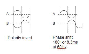
You can read a bit more here about the distinction between the two, including what "phase shifts" really mean in audio terms, but the lesson here is to watch your waveforms and be careful of what your audio settings are actually doing to the signal, regardless of how they're labelled.
Reading Your Audio
I've referred to a few tools for watching and "reading" the characteristics of audio we've been discussing. For clarity's sake, in this section I'll review exactly, for practical purposes, what tools and monitors you can look at to keep track of your audio.
Level Meters

Level meters are crucial to measuring signal level and will be where you see scales such as dBu, dBFS, VU, etc. In both analog and digital form, they're often handily color-coded; so if after all of this, you still don't really get the difference between dBu and dBFS, to some degree it doesn't matter: level meters will warn you when levels are getting too hot by changing from green to yellow and eventually to red when you're in danger of getting too "hot" and clipping (whatever that equivalent point is in the scale in question).
Waveform
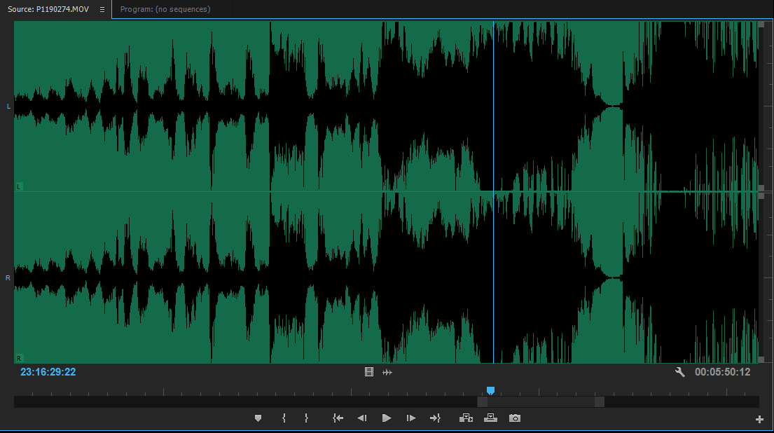
Waveforms will actually chart the shape of an audio wave; they're basically a graph with time on the x-axis and amplitude (usually measured in voltage) on the y-axis. These are usually great for post-digitization quality control work, since they give an idea of audio levels not just in any one given moment but over the whole length of the recording. That can alert you to issues like noise in the signal (if, say, the waveform stays high where you would expect more fluctuation in a recording that alternates loud and quiet sections) or unwanted shifts in polarity.

Waveform monitors can sometimes come in the form of oscilloscopes: these are essentially the same device, in terms of showing the user the "shape" of the audio signal (the amplitude of the wave based on voltage). Oscilloscopes tend to be more of a "live" form of monitoring, like level meters - that is, they function moment-to-moment and require the audio to be actively playing to show you anything. Digital waveform monitors tend to actually save/track themselves over time to give the full shape of the recording/signal, rather than just the wave at any one given moment.
Spectrogram
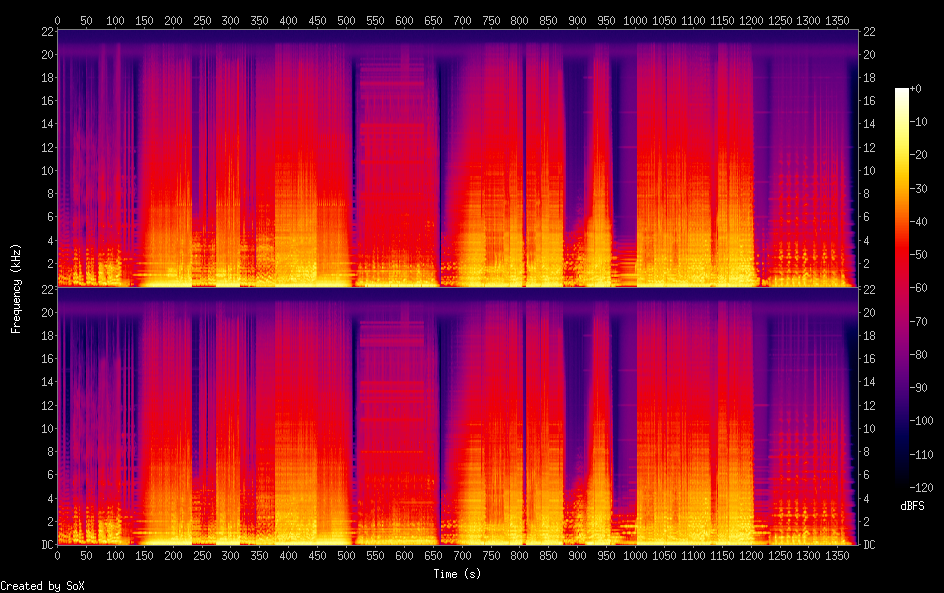
Spectrograms help with a quality of audio that we haven't really gotten to yet: frequency. Like waveforms, they are a graph with time on the x-axis, but instead of amplitude they chart audio wave frequency.
If amplitude is perceived by human ears as loudness, frequency is perceived as pitch. They end up looking something like a "heat map" of an audio signal - stronger frequencies in the recording show up "brighter" on a spectrogram.
Spectrograms are crucial to audio engineers for crafting and recording new signals, "cleaning up" audio signals by removing unwanted frequencies. As archivists, you're probably not actually looking to mess or change with the frequencies in your recorded signal, but they can be helpful for checking and controlling your equipment; that is, making sure that you're not introducing any new noise into the audio signal in the process of digitization. Certain frequencies can be dead giveaways for electrical hum, for example.
The More You Know
This is all a lot to sift through. I hope this post clarifies a few things - at the very least, why so much of the language around digitizing audio, and especially digitizing audio for video, is so muddled.
I'll leave off with a few general tips and resources:
- Get to know your equipment. Test audio reference signals as they pass through different combinations of devices to get an idea what (if anything) each is doing to your signal. The better you know your "default" position, the more confidently you can move forward with analyzing and reading individual recordings.
- Get to know your meters. Which one of the scales I mentioned are they using? What does that tell you? If you have both analog and digital meters (which would be ideal), how do they relate as you move from one to the other?
- Leave "headroom". This is the general concept in audio engineering of adjusting voltage/gain/amplitude so that you can be confident there is space between the top of your audio waveform and "clipping" level (wherever that is). For digitization purposes, if you're ever in doubt about where your levels should be, push it down and leave more headroom. If the choice is between capturing the accurate shape of an audio signal, albeit too "low", there will be opportunity to readjust that signal again later as long as you got all the information. If you clip when digitizing, that's it - you're not getting that signal information back and you're not going to be able to adjust it.
"What is the difference between level, volume and loudness?", David Mellor
"What is the difference between dBFS, VU and dBU [sic] in Audio Recordings?", Emerson Maningo
"Understanding & Measuring Digital Audio Levels", Glen Kropuenske
"Audio" error entries on the AV Artifact Atlas
